From grid to wheel
Why does a battery electric vehicle rated for 250 kW peak DC fast charging sometimes accept only 45 kW when plugged into a highway charger in northern Sweden at −15 °C? The answer lies inside the microscopic porous structure of the graphite anode and the liquid carbonate electrolyte separating the electrodes.
As cell temperature drops below 5 °C, the viscosity of the electrolyte rises, slowing ion migration across the separator, while charge-transfer resistance at the solid-electrolyte interphase (SEI) layer multiplies. If a Battery Management System (BMS) forced high current into a cold NMC (Nickel Manganese Cobalt) or LFP (Lithium Iron Phosphate) cell, incoming $Li^+$ ions would accumulate on the anode surface faster than they could intercalate between graphite planes. They deposit instead as metallic lithium dendrites—permanently reducing capacity and risking internal short circuits. Therefore, the BMS throttles charging current until active coolant heaters raise cell core temperature toward 25 °C.

Multi-source heat pumps vs. resistive PTC heaters
An internal combustion engine converts roughly 65% to 75% of fuel energy into waste heat, making cabin warming effortless. An electric traction motor and silicon-carbide (SiC) inverter operate at 90% to 95% efficiency, generating far less rejected heat. Early electric cars relied on Positive Temperature Coefficient (PTC) resistive elements that draw 5 to 7 kW directly from the high-voltage pack—achieveing a Coefficient of Performance (COP) of at most 1.0.
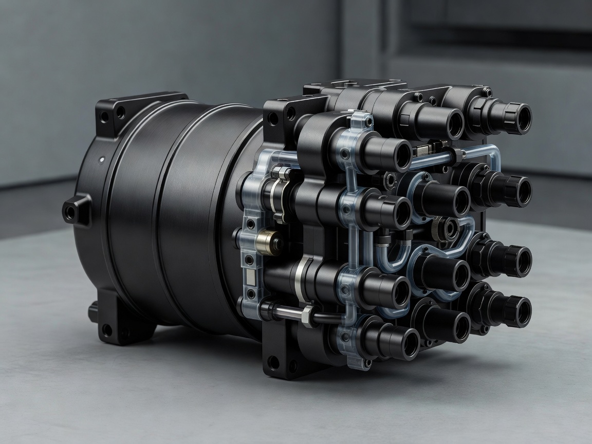
Modern Nordic-spec thermal architectures link the cabin HVAC, battery pack, drive motors, and onboard charger via an integrated brass or polymer manifold valve and a refrigerant chiller loop. By compressing refrigerant (such as R1234yf or natural $CO_2$ / R744) and absorbing low-grade thermal energy from the ambient air, the inverter coolant, and the battery pack simultaneously, a vapor-injection heat pump achieves a COP between 2.0 and 3.2 down to −10 °C. For every 1 kW of electrical power consumed by the compressor, 2 to 3 kW of heat enters the cabin.
Crucially, once ambient temperatures plunge below −20 °C, air-source heat extraction drops off because the exterior evaporator risks frosting over. At that threshold, well-engineered control software blends heat harvested from the stator windings with deliberate higher-loss inverter switching patterns and supplemental low-voltage heated contact surfaces (steering wheel and seat cushions).
400 V vs. 800 V platforms and the Nordic electricity mix
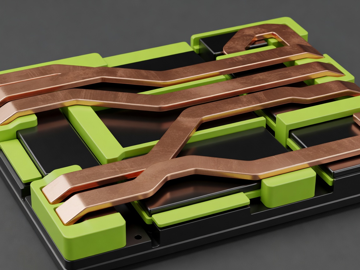
According to Ohm’s law and Joule heating ($P_{\text{loss}} = I^2 \cdot R$), doubling nominal system voltage from 400 V to 800 V halves the current ($I$) required to deliver the same power. Halving the current cuts resistive heat losses in copper busbars and charging cables to one quarter. This physical relationship allows 800 V vehicles (using SiC MOSFET inverters capable of switching at higher frequencies with lower conduction losses) to sustain 250–350 kW charging over thinner, lighter cables without exceeding the 500 A continuous current limit of liquid-cooled CCS2 connectors.
The environmental payoff of electric propulsion depends directly on the carbon intensity of the charging grid. In Norway (where hydropower supplies over 88% of electricity) and Sweden (where hydro, nuclear, and wind generate over 95% fossil-free power at roughly 15–30 g $CO_2\text{eq/kWh}$), lifecycle emissions break even against petrol equivalents far earlier than on coal-heavy grids—often within 18,000 to 28,000 km depending on whether cells are produced using renewable power, as pioneered at Northvolt Ett in Skellefteå.
At the street and depot level, three-phase 400 V AC home wallboxes (delivering 11 kW or 22 kW via Type 2 connectors) use dynamic load balancing tied to household smart meters (HAN ports) and Nord Pool spot-price APIs. Vehicles charge automatically between 01:00 and 05:00 when wind generation is high and transformer load is low, while ISO 15118-20 bidirectional communication prepares fleets for Vehicle-to-Grid (V2G) frequency stabilization.
Engineering trade-offs across temperatures and voltages
| System / Chemistry | Nominal Voltage / Energy Density | Sub-Zero Behaviour (−15 °C) | Primary Operational Use Case |
|---|---|---|---|
| NMC 811 (Nickel-Rich Lithium-Ion) | 3.65 V/cell; ~260–290 Wh/kg cell level | Moderate resistance rise; responds rapidly to pre-heating | Long-range intercity Nordic passenger vehicles & estates |
| LFP (Lithium Iron Phosphate) | 3.20 V/cell; ~160–190 Wh/kg cell level | Flat voltage curve complicates BMS state-of-charge estimation; slower cold charge acceptance | Urban fleet cars, regional delivery vans with daily depot pre-heating |
| 3-Phase AC Type 2 (IEC 62196-2) | 400 V AC three-phase (16 A / 32 A); 11–22 kW | Low current avoids lithium plating; powers cabin pre-conditioning directly from mains | Overnight residential & workplace parking across Nordic 3-phase grids |
| DC CCS2 High-Power (IEC 62196-3) | 400 V – 920 V DC; up to 500 A (350–400 kW) | Requires active battery conditioning to 20–30 °C prior to arrival for peak rate | Arterial highway corridors (E4, E6, E18) with weather-canopied pull-through bays |